
What Is Clamping Force and Why Your Rated Capacity Isn’t the Full Story

Kakuta FA300 latch-action toggle clamp on a dark background, with the title "What Is Clamping Force — and Why Rated Capacity Isn't the Full Story" and the Kakuta logo.
Kakuta toggle clamp holding a workpiece on a machining fixture
A toggle clamp's rated capacity is only the starting point for safe fixture design.

By the Kakuta Engineering Team · Reading time: ~6 minutes

Every toggle clamp spec sheet leads with one number: the rated holding capacity. It's printed in bold, measured in daN, and it's the figure most engineers use to compare one clamp against another. But if you specify a clamp on rated capacity alone, you're working with only part of the picture.

Rated capacity tells you what a clamp can hold under ideal, controlled test conditions. It does not tell you how much of that force you can rely on in a real fixture, under real loads, cycle after cycle. The gap between those two numbers is where fixture problems begin — parts that shift under machining loads, clamps that loosen over a production run, and holding force that quietly disappears when the geometry isn't ideal.

This guide explains what clamping force actually means, how rated capacity differs from the force you can count on in service, and how to apply a safety factor so your fixture holds reliably. If you're still deciding which clamp type to specify in the first place, start with our guide on how to choose the right toggle clamp for your application.

What Clamping Force Actually Means

Clamping force — also called holding force or hold-down force — is the force a toggle clamp applies to keep a workpiece secured against a fixture or work surface. In toggle clamp specifications it's most commonly expressed in daN (decanewtons), where 1 daN is approximately 1 kilogram-force, or about 2.25 pounds-force.

It helps to separate two related ideas that are easy to confuse:

  • Holding capacity — the maximum force the clamp can resist at the clamping point before the toggle mechanism gives way. This is the rated number on the spec sheet.
  • Applied clamping force — the actual force pressing your workpiece down in service, which depends on how the clamp is set, the spindle or bar position, and the fixture geometry.

The distinction matters because a toggle clamp is a mechanism, not a constant-force device. Its force output changes with the position of the linkage, the adjustment of the spindle, and the direction of the load it's resisting. The rated number is a peak figure measured under specific test conditions — not a guarantee of what you'll get in your setup.

Rated Capacity vs. Working Capacity: Reading the Spec Sheet Correctly

When a manufacturer lists a holding capacity — say 400 daN for a mid-range horizontal-handle clamp — that value is established on a test rig where the load is applied in the ideal direction, the clamp is in its optimal locked position, and nothing is vibrating, heating, or cycling thousands of times. Your fixture is rarely that tidy.

Kakuta toggle clamp securing a workpiece in a real production fixture
Rated capacity is a peak lab figure; working capacity is what remains once real-world conditions are accounted for.

Several factors reduce the force you can actually rely on:

  • Load direction. Rated capacity assumes force resisted along the clamp's designed axis. Off-axis or side loads reduce effective holding force.
  • Spindle and bar adjustment. A clamp set slightly short or long of its ideal position delivers less than its rated force.
  • Vibration and cyclic loading. Machining, drilling, and welding introduce dynamic loads that a static rating never captures.
  • Wear over the production run. Pivots, bushings, and rubber spindle caps wear, and holding force drifts down across thousands of cycles.
  • Workpiece surface and rigidity. A flexible part or an uneven surface changes how force is distributed.

The practical takeaway: treat rated capacity as a ceiling you should never design up to. The force you plan around — the working capacity — should be a deliberate fraction of that rating. That fraction is set by your safety factor.

What Is a Safety Factor — and How to Apply It

A safety factor is the margin between a component's rated capacity and the load you actually place on it. It's the engineer's buffer against everything the rating doesn't account for: variation, wear, dynamic loads, and simple uncertainty.

Applying it to clamp selection is straightforward:

Required rated capacity = Estimated working load × Safety factor

Worked through in four steps:

  1. Estimate the working load. Determine the maximum force trying to move, lift, or shift your workpiece — cutting forces, part weight, tool thrust, or process reaction forces.
  2. Choose a safety factor appropriate to your application (see the table below).
  3. Multiply the working load by the safety factor to find the minimum rated capacity you need.
  4. Select a clamp whose rated holding capacity meets or exceeds that figure — then distribute the load across multiple clamps if a single unit would be over-stressed.

A simple example: if your process applies an estimated 120 daN of working load and you're using a 2.5× safety factor for light machining, you need a clamp rated for at least 300 daN (120 × 2.5). Specifying a 300 daN clamp gives you the margin to absorb vibration, wear, and off-axis loading without the part shifting.

Suggested Safety Factors by Application Type

These are practical starting ranges. Always adjust for your own process, tolerances, and risk. When in doubt, size up.

Application Typical Safety Factor Why
Light assembly / hand work 1.5× – 2× Low, predictable static loads; minimal vibration.
General machining / drilling 2× – 3× Moderate cutting forces and cyclic loading.
Welding / heavy fixturing 3× – 4× Thermal distortion, heavier parts, higher consequences of movement.
Automated / high-cycle production 3× – 5× Thousands of cycles amplify wear; unattended operation raises risk.

Common Clamping Force Mistakes to Avoid

  • Designing to the rated number. Specifying a clamp whose rating exactly matches your working load leaves no margin for anything real.
  • Ignoring load direction. A clamp rated for a downward hold-down load may offer far less resistance to a sideways push.
  • Forgetting dynamic loads. Static part weight is easy to calculate; the cutting, thrust, and impact forces of the process are what actually challenge the clamp.
  • Over-clamping. Too much force can deform delicate parts or overload the fixture. A safety factor works in both directions — it's about the right force, not simply the most.
  • Using one clamp where several belong. Distributing load across multiple clamps improves stability and keeps each unit within a safe working range.
Kakuta VH Series heavy-duty vertical toggle clamp
A heavy-duty clamp like the VH Series gives you the rated headroom to build in a proper safety margin.

Matching a Kakuta Series to Your Force Range

Kakuta has manufactured precision toggle clamps since 1959, with series spanning light assembly through heavy-duty, high-force workholding. Choosing the right family is the first step in giving yourself the safety margin above:

For full ratings and mounting dimensions across every model, browse our complete product range, or read the companion guide on choosing the right toggle clamp for your application.

For deeper background on the physics of clamping, the engineering reference Engineering Toolbox offers useful primers on force, friction, and mechanical advantage.

Unsure which safety factor applies to your fixture?

Send us your application details and our engineering team will recommend a clamp and force range with the right margin built in.

Contact Us for a Spec Review

The Bottom Line

Rated capacity is where clamp selection starts, not where it ends. It's a peak figure from an ideal test — a ceiling, not a target. Reliable fixture design means estimating your real working load, applying a safety factor suited to the application, and choosing a clamp whose rating gives you room to absorb the vibration, wear, and off-axis loads that every real process produces.

Get that margin right and your workholding stays consistent from the first part to the ten-thousandth. Get it wrong, and the failure shows up exactly where you can least afford it — mid-production, on the shop floor.

Talk to our engineering team about your application, or explore the full Kakuta range to find the right series for your force requirements.

Read More
Engineering Guides Ajariya Wunseesang Engineering Guides Ajariya Wunseesang

How to Choose the Right Toggle Clamp for Your Application

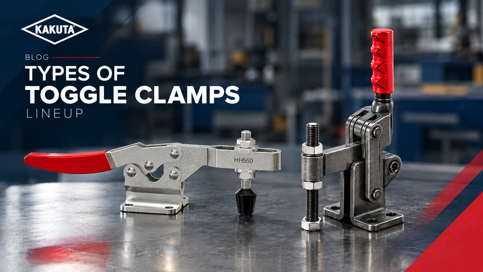
Kakuta toggle clamp types lineup — HH horizontal handle, HV vertical handle, FA straight-line action, SL latch action, AC air clamp, FM mini, and PA pneumatic toggle clamps for industrial workholding

Kakuta toggle clamp types lineup — HH horizontal handle, HV vertical handle, FA straight-line action, SL latch action, AC air clamp, FM mini, and PA pneumatic toggle clamps for industrial workholding

Kakuta toggle clamp types lineup — HH horizontal handle, HV vertical handle, FA straight-line action, SL latch action, AC air clamp, FM mini, and PA pneumatic toggle clamps for industrial workholding

Choosing the wrong toggle clamp does not announce itself immediately. The fixture closes. The part seats. Production begins. Then, three weeks later, a clamp fails mid-cycle, a part shifts during welding, or an operator compensates with a workaround that becomes a safety concern.

The right toggle clamp is not simply the one that fits the mounting footprint. It is the one that matches the direction of your clamping force, the geometry of your fixture, the cycle rate of your production line, and the environment your equipment works in.

This guide covers the seven main toggle clamp types available in the Kakuta range, the critical questions to answer before you specify, and how to match both to the series designed for your application.

What Is a Toggle Clamp?

A toggle clamp is a mechanical workholding component that uses over-center geometry to lock a workpiece in position. When the handle passes through the center point of the toggle linkage, the clamp achieves a self-locking state — holding the part securely without any continuous operator force applied.

This over-center locking principle is what distinguishes toggle clamps from simple mechanical clamps. Once locked, the clamp maintains holding force through the full machining, welding, or assembly cycle, releasing only when the operator deliberately opens the handle.

Toggle clamps are used across jig and fixture applications, assembly lines, welding fixtures, CNC machining setups, and quality inspection stations wherever a workpiece must be held in a precise, repeatable position.

Kakuta has been manufacturing precision toggle clamps since 1959. The product range spans standard, heavy-duty, latch-action, pneumatic, and compact models, covering holding capacities from light assembly applications to demanding automotive and structural jig environments.

Diagram showing toggle clamp over-center geometry — pivot point, clamping force direction, and locked position for industrial jig and fixture applications.

The 7 Main Toggle Clamp Types

Understanding the fundamental difference between clamp types is the first step in the selection process. Each type is optimised for a different force direction and fixture geometry.

Horizontal Handle Clamps (HH Series)

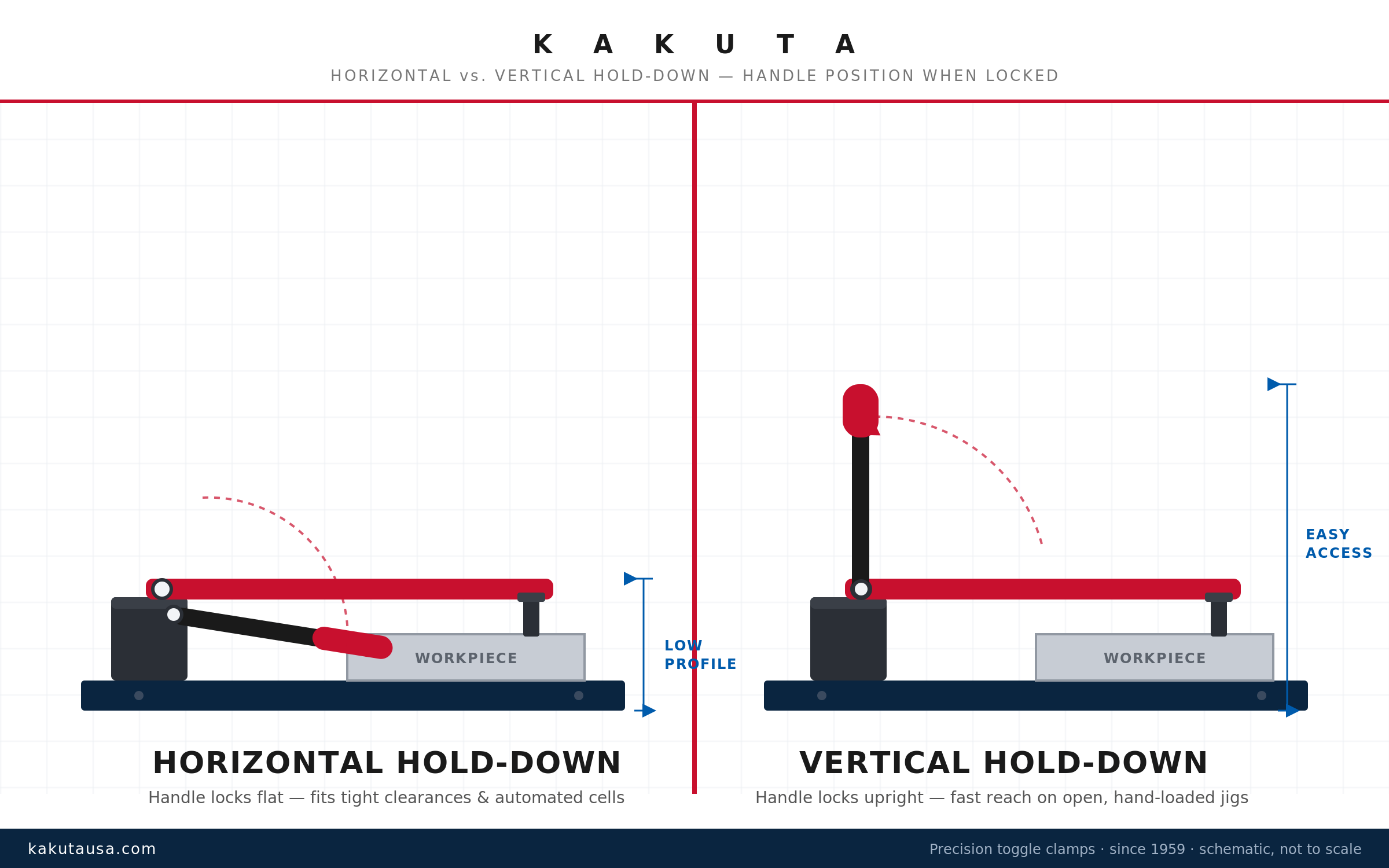
The horizontal handle clamp is the most widely used toggle clamp type in general manufacturing. The handle operates in a horizontal plane, and the clamping spindle applies a vertical, downward hold-down force onto the workpiece.

HH series clamps are suited to applications where the operator has clear horizontal access to the handle, and where the primary clamping force direction is downward — holding a part onto a fixture base or machine table. They perform well in high-frequency production environments and are available in a broad range of holding capacities.

Typical applications include CNC machining fixtures, general assembly jigs, and inspection fixtures where space allows horizontal handle travel.

→ Explore the Kakuta HH Series

Vertical Handle Clamps (HV Series)

The vertical handle clamp operates with a handle that moves in a vertical plane. The clamping spindle delivers a downward or angled force depending on the model configuration.

HV series clamps are preferred where fixture geometry limits horizontal access — for example, in nested or multi-clamp fixtures where handles must not interfere with each other or with the workpiece approach path. They are also common in applications where the operator position makes a vertical handle stroke more ergonomically efficient.

For heavy-duty applications requiring holding forces from 300 daN up to 2,400 daN, Kakuta's VH Series (heavy-duty vertical handle clamps) provides an extended capacity range suited to automotive jig fixtures, structural holding applications, and high-cycle production lines where standard-duty clamps are insufficient.

→ Explore the Kakuta HV Series

Straight-Line Action Clamps (FA Series)

The straight-line action clamp, also called a push-pull clamp, delivers force in a linear direction — directly along the axis of the spindle travel. Unlike horizontal or vertical handle clamps, the FA series applies force horizontally inward or outward rather than downward.

This makes straight-line action clamps the correct choice where the workpiece must be pushed against a locating stop, pulled into a nest, or clamped from the side rather than from above. The inline force delivery also makes FA series clamps easier to integrate into fixtures where overhead clearance is restricted.

Common applications include side-clamping in welding fixtures, inline locating jigs, and assembly stations where a part must be pushed positively to a datum before clamping.

→ Explore the Kakuta FA Series

Latch Action Clamps (SL Series)

The latch action clamp — Kakuta's SL series — operates with a side-entry handle and a horizontal plunger that drives directly into the fixture to lock the workpiece. The action is a firm, decisive push-and-lock motion, making it fast to operate and easy to build into tight fixture layouts where a conventional horizontal or vertical handle would create interference.

SL series clamps are particularly well suited to applications where the clamp must engage from the side of the workpiece rather than from above, and where quick, consistent locking and release are required. The compact body profile allows SL clamps to be positioned closely together in multi-clamp fixtures without handle collision.

Typical applications include assembly jigs, inspection fixtures, sheet metal holding applications, and any production environment where operator speed and clamp accessibility matter as much as holding force.

→ Explore the Kakuta SL Series

Air Clamps (AC Series)

Kakuta's AC series air clamps replace the manual handle with a pneumatic actuator, enabling automated clamping and unclamping as part of a machine cycle or PLC-controlled sequence. The pneumatic mechanism drives the same over-center toggle geometry used in manual clamps, delivering consistent holding force on every cycle without operator involvement.

AC series clamps are specified when cycle rate demands exceed practical manual operation, when the fixture is integrated into an automated production cell, or when operator ergonomics require removing the manual clamping step from the production cycle entirely. They are readily integrated into existing pneumatic circuits and machine control systems.

Common applications include robotic welding cells, automated assembly lines, high-volume CNC production fixtures, and any environment where repeatable, hands-free clamping is a production requirement.

→ Explore the Kakuta AC Series

Mini Toggle Clamps (FM Series)

The FM series covers Kakuta's compact and miniature toggle clamp range — precision workholding components engineered for applications where space is severely constrained and standard-size clamps cannot be accommodated without fixture redesign.

FM series clamps retain the same over-center locking geometry and reliable hold-down action as full-size Kakuta clamps, scaled down to a fraction of the footprint. They are used in small-part assembly fixtures, electronics manufacturing, optical component handling, laboratory equipment, and any application where the workpiece itself is small or where fixture density requires multiple clamps in a very limited area.

Despite their compact size, FM series clamps deliver consistent, repeatable holding force appropriate for precision light-duty and medium-duty applications.

→ Explore the Kakuta FM Series

Pneumatic Toggle Clamps (PA Series)

Kakuta's PA series pneumatic toggle clamps combine the mechanical over-center locking action of a manual toggle clamp with a pneumatic cylinder that drives the clamping arm automatically. Unlike the AC air clamp — which replaces the full toggle mechanism with a pneumatic actuator — the PA series retains the familiar toggle clamp body and adds pneumatic actuation to it, making the transition from manual to automated clamping straightforward in existing fixture designs.

PA series clamps are well suited to semi-automated and fully automated production environments where consistent clamping force and cycle-accurate repeatability are required. They are commonly used in welding fixtures, assembly automation, and production lines where a manual operator step needs to be eliminated without completely redesigning the fixture layout around a different clamp body.

Integration with a pneumatic circuit is direct, and the toggle mechanism's self-locking geometry provides a mechanical backup even under pressure fluctuations.

→ Explore the Kakuta PA Series

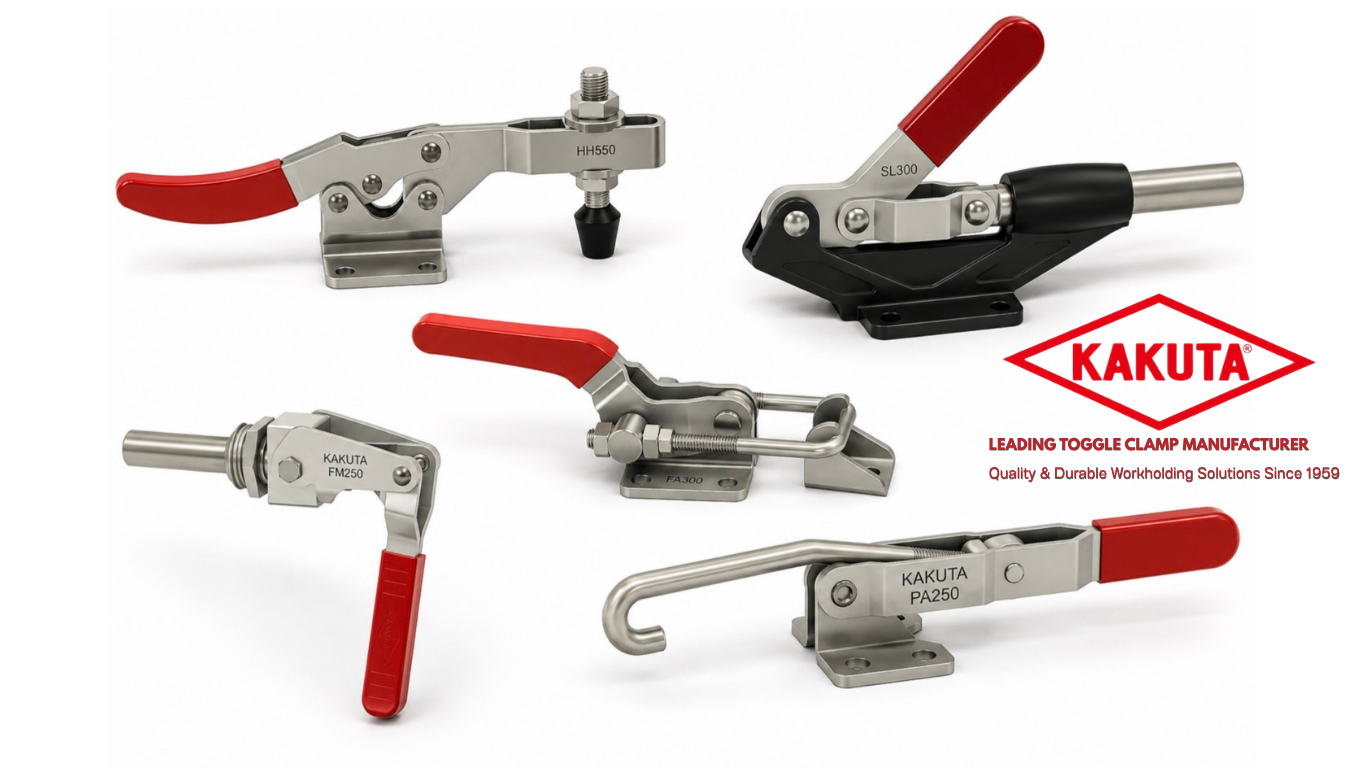
Seven Kakuta toggle clamp types comparison — HH, HV, FA, SL, AC, FM, and PA pneumatic toggle clamps for industrial workholding and jig fixture applications

5 Questions to Ask Before You Specify a Toggle Clamp

Once you know which clamp type fits your force direction and fixture geometry, these five questions will define the correct model within that type.

1. What direction is your primary clamping force? This is the first filter. Downward vertical force points to the HH or HV series. Horizontal inline force points to the FA or SL series. If clamping is automated and integrated into a machine cycle, evaluate the AC or PA series — AC for full actuator-based clamping, PA for pneumatic automation of a toggle clamp body. For small-part or compact fixture work, evaluate the FM series against the space constraints first. Getting the force direction wrong makes every other decision irrelevant.

2. What is the required holding capacity? Catalogue holding capacity is a rated maximum — not a working load. In practice, most fixture engineers apply a safety factor of 2:1 to 3:1 against the actual clamping force required by the application. For light assembly work, the FM mini series or standard HH or SL clamps are sufficient. For heavy jig applications, automotive fixtures, or structural workholding requiring 1,000 daN and above, Kakuta's VH heavy-duty series provides verified holding capacity up to 2,400 daN.

3. What is your part's geometry and surface condition? A flat, machined surface clamps differently from a curved or coated workpiece. Spindle tip selection — flat tip, neoprene tip, or swivel spindle — should match the workpiece contact geometry. Clamp arm height and reach must accommodate the workpiece profile without interference.

4. How many cycles per shift does your fixture run? A fixture running 200 cycles per shift operates differently from one running 2,000. Higher cycle rates accelerate wear on pivot pins, spindle threads, and handle mechanisms. For high-cycle environments, select models from Kakuta's range with appropriate structural ratings, or specify the PA or AC pneumatic series to remove manual wear from the equation and ensure consistent, repeatable clamping on every cycle.

5. Does the environment require corrosion resistance or special surface treatment? Standard production environments are served by Kakuta's standard surface finish. For wet machining environments, chemical exposure, or food and beverage applications, confirm the clamp finish and material specifications match the environmental requirements. Where European industrial standards are a reference, Kakuta's VH series corresponds directly to the VA series specifications used by UK and European fixture engineers.

Kakuta precision toggle clamps

Matching the right series to your application

Use this reference to identify the correct Kakuta clamp series based on your application type, holding force requirements, and fixture geometry.

Series Application Key consideration
HH Series General machining fixture, CNC setup Downward hold-down force with horizontal handle travel. Best where the operator has clear lateral access to the handle.

Most widely used toggle clamp type in general manufacturing

HV Series Multi-clamp fixture, limited lateral space Vertical handle travel in a compact footprint. Preferred where horizontal access is restricted by fixture geometry or operator position.

Well-suited to nested fixtures and ergonomic overhead clamping

VH Heavy-Duty Automotive jig, structural fixture High holding force from 300 – 2,400 daN. Built for high-cycle production lines where standard-duty clamps are insufficient.

Japanese precision equivalent to VA Series (UK/EU) and Serie Verticale Pesante (Italy)

FA Series Side-clamping, inline locating fixture Linear push-pull force along the spindle axis. The correct choice where overhead clearance is restricted or the part must be pushed to a datum.

Common in welding fixtures and side-clamping assembly stations

SL Series Fast side-entry latch, multi-clamp layout Latch action with compact body. Fast push-and-lock operation where handles must not interfere with adjacent clamps or workpiece approach.

Sheet metal holding, assembly jigs, dense multi-clamp fixtures

AC Series Automated production cell, robotic welding Full pneumatic actuation replaces the manual toggle mechanism for PLC-integrated, hands-free clamping on every cycle.

High-volume CNC fixtures and robotic cells requiring automated operation

FM Series Small-part fixture, compact or dense layout Miniature footprint with full over-center locking action. For fixtures where standard-size clamps cannot be accommodated.

Electronics, optical components, precision light-to-medium-duty assembly

PA Series Semi-automated fixture, toggle body + pneumatic drive Pneumatic actuation added to a standard toggle clamp body. Retains over-center mechanical backup under pneumatic pressure fluctuation.

Welding fixtures and assembly automation transitioning from manual clamping

Kakuta toggle clamp mounted on industrial jig fixture holding a metal workpiece — precision workholding in manufacturing application

A Note on Heavy-Duty Applications and European Equivalents

For engineers currently specifying heavy-duty vertical toggle clamps from European sources — including VA series clamps from UK manufacturers or the Serie Verticale Pesante from Italian suppliers — Kakuta's VH series provides directly equivalent holding capacities and a comparable product range.

The VH 100 through VH 602 series spans 300 daN to 2,400 daN nominal holding force, covering the same capacity range as the heavy-duty vertical series available from European manufacturers, with Japanese precision engineering and global distribution from the USA platform.

For engineers transitioning from another brand or cross-referencing a current specification, Kakuta's technical team can assist with direct model equivalency confirmation.

→ Contact Kakuta USA for a cross-reference

Conclusion

Selecting the right toggle clamp comes down to four variables: force direction, holding capacity, cycle rate, and environment. The clamp type — HH, HV, FA, SL, AC, FM, or PA — follows from the force direction and fixture geometry. The series and model follow from the remaining variables.

Kakuta's product range has been engineered since 1959 to cover every standard workholding application, from compact FM mini clamps for small-part fixtures to heavy industrial VH jigs requiring over 2,000 daN of holding force. The selection framework above applies regardless of the industry or scale of production.

If your application falls outside standard parameters — unusual fixture geometry, extreme cycle rates, or heavy-load structural holding — contact Kakuta USA directly. The right clamp specification is worth the conversation.

→ Explore the full Kakuta toggle clamp catalog   → Contact Kakuta USA for technical support

Kakuta has been manufacturing precision toggle clamps since 1959. Products are available through authorized distributors across North America and globally. For specification support, contact Kakuta USA.

Read More